
Workshop #3 - Introduction to Fins
Assignment: Look at the definition of fin efficiency and how that relates to the temperature distribution in a fin. Compare measured and theoretical values.
In this workshop you use the thin piece of aluminum as a fin that is powered with the thin-film heater supplied with the kit. The heat flux gage can be used to measure the total heat transfer supplied to the fin. The fin efficiency has a simple definition of this actual heat transfer relative to the maximum heat transfer that would occur if the entire fin was at the base temperature.
h is the heat transfer coefficient, Af is the total surface area of the fin, qf is the actual heat transfer from the fin.
Af = 2*w*L + 2*t, where w = width, L = length from the base, and t = thickness.
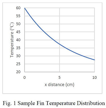
Fig. 1 shows an example of a typical temperature distribution along the length of a fin. Fig. 2 is a picture of the aluminum fin supplied as mounted on the heater and heat flux sensor.
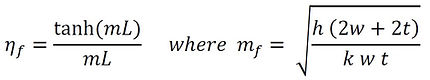
The theory for a straight fin gives the fin efficiency as
in terms of the heat transfer coefficient, h, and the thermal conductivity of the fin, k. The hyperbolic tangent function (tanh) is a special exponential function. The values can be determined on some calculators or looked up online.


Workshop #3 - Fin Results
Your challenge is to measure the heat transfer from the fin supplied and calculate the fin efficiency. Before starting, measure the size of the fin and record the dimensions. As shown in the figure, place the heater on any low conductivity surface followed by the heat flux gage and small end of the thin aluminum sheet. Use the small wood block to hold all of this in place. This arrangement will force most of the power from the heater through the heat flux sensor to the high conductivity aluminum sheet to then dissipate to the air. Turn on the heater and data acquisition system. Allow the system to come to equilibrium, which may take five to ten minutes. This will be clear when the temperature and heat flux measured by the sensor become nearly constant. Record these values. Make sure the second thermocouple is away from the fin out in the room.
The size of the heater is 1 inch by 1.2 inch, which gives a surface area of Ah = 7.75 cm^2. Use this area with the measured heat flux to find the total input heat transfer that the fin dissipates to the air, q = q" Af. The fin is aluminum, which has a thermal conductivity of k = 175 W/m-K. The exposed surface of the fin will be twice the length times the width (neglecting the very thin edges). Because the effects of radiation can be approximately included in the heat transfer coefficient, treat the problem as shown in the introduction as being purely convection from the fin and conduction in the fin. Initially, assume the overall heat transfer coefficient from the fin to the air is h = 15 W/m^2-K.
1. Measured Values:
Heat Flux, q" =
Sensor Temperature, Ts =
Air Temperature, T∞ =
Fin heat transfer, q =
Fin width, w =
Fin length, L =
Fin thickness, t = 0.32 mm
Fin area, Af =
Fin efficiency, ηf =
2. Compare the measured results with theory using the equations given for a straight fin:
mf =
mfL =
ηf =
3. How do these values compare with what was measured?
4. What would be a more appropriate value of heat transfer coefficient to make the theory and measurements match better?
5. Feel the temperature distribution along the fin with your fingers. Does it match what you would expect?
